


Case Duration:
November 2020 – Present (3+ Years)
Client Background:
The Chemical Branch of ZTHC Energy Co., Ltd. operates China's largest coal-to-olefins facility with
Client Background
The Chemical Branch of ZTHC Energy Co., Ltd. operates China's largest coal-to-olefins facility with:
1. Total investment: CNY 60 billion
2. Annual production capacity:
1) 3.6 million tons methanol (intermediate product)
2) 1.37 million tons polyolefins
3. Designation:
1) National coal deep-processing demonstration project
2) Key project of Inner Mongolia Autonomous Region
Client Requirements & Solutions
Predictive Maintenance System for Centralized Equipment Management
Comprehensive Predictive Maintenance System:
1. Monitors 340+ critical equipment units across:
1) 19 production units
2) 6 operational departments
2. Covers key assets including:
1) Extruders
2) Compressors
3) Coal mills
4) Pumps & fans
3. Provides:
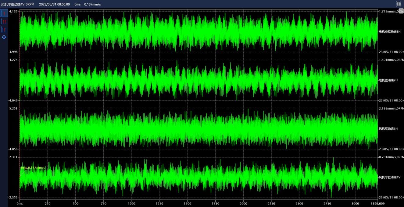
1) Early anomaly detection
2) Precise fault localization
3) Degradation trend analysis
Plant-wide Centralized Control:
1. Integrated predictive maintenance system with RONDS Remote O&M Center
2. "Edge-Cloud" collaborative monitoring architecture
3. Unified equipment status dashboard
Application Value
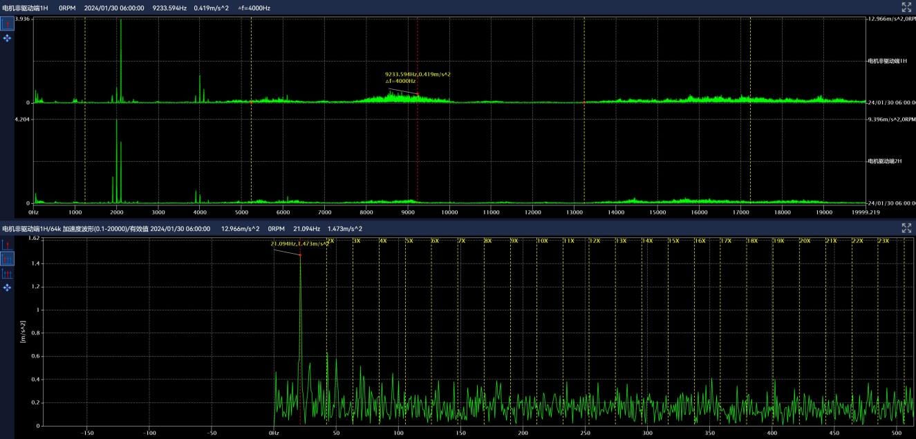
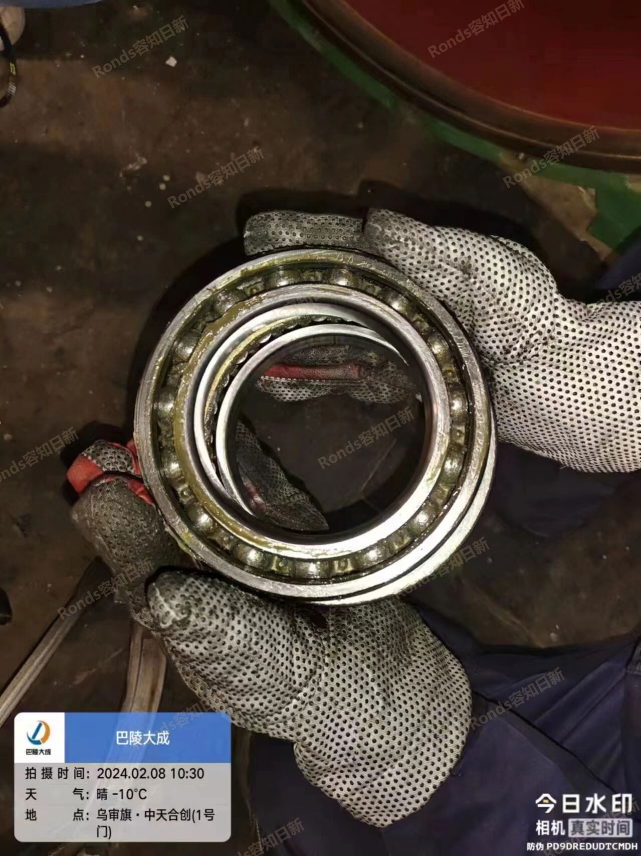
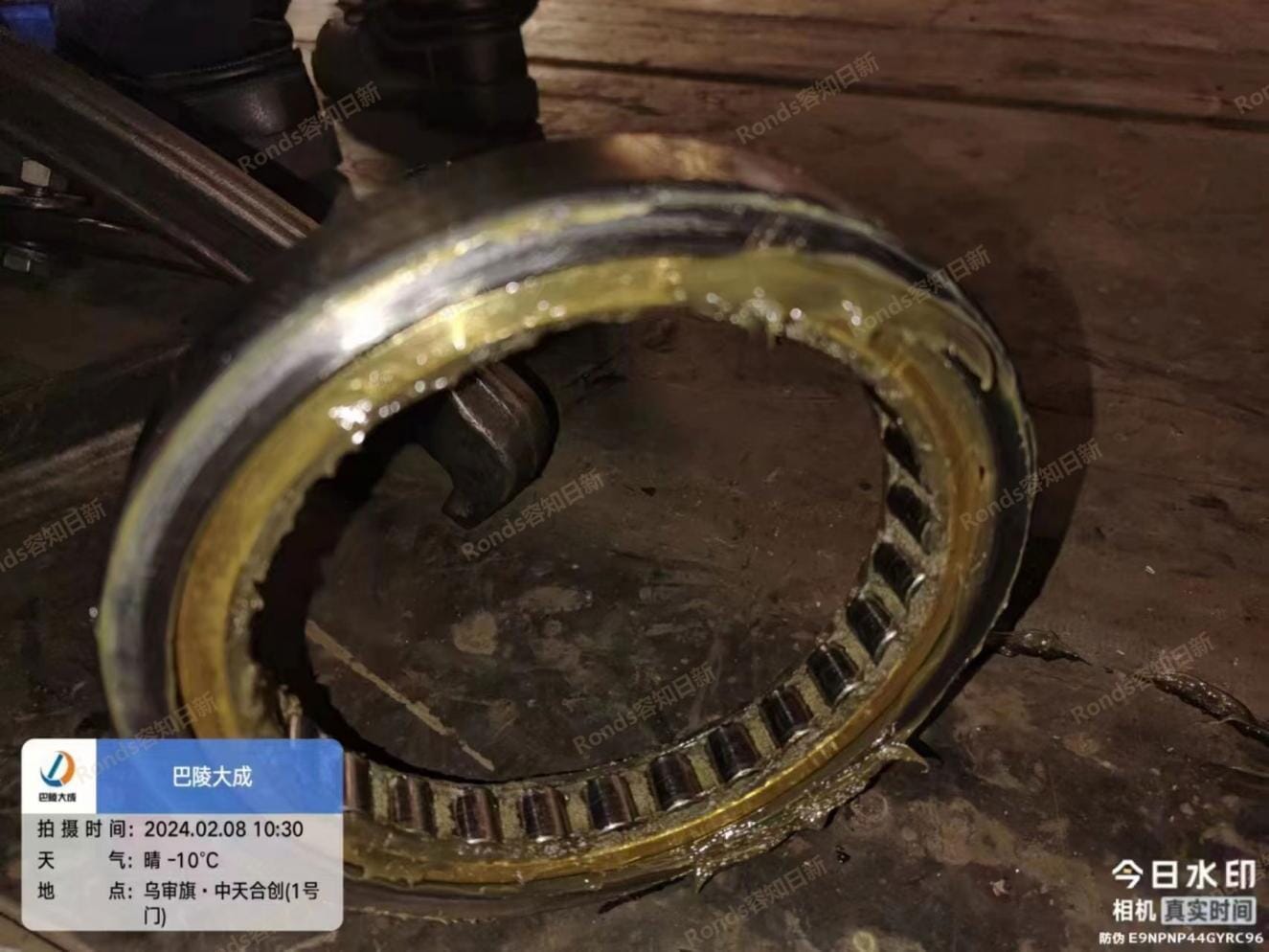
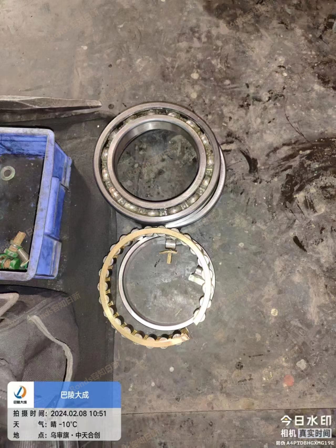
24/7 Equipment Monitoring & Control:
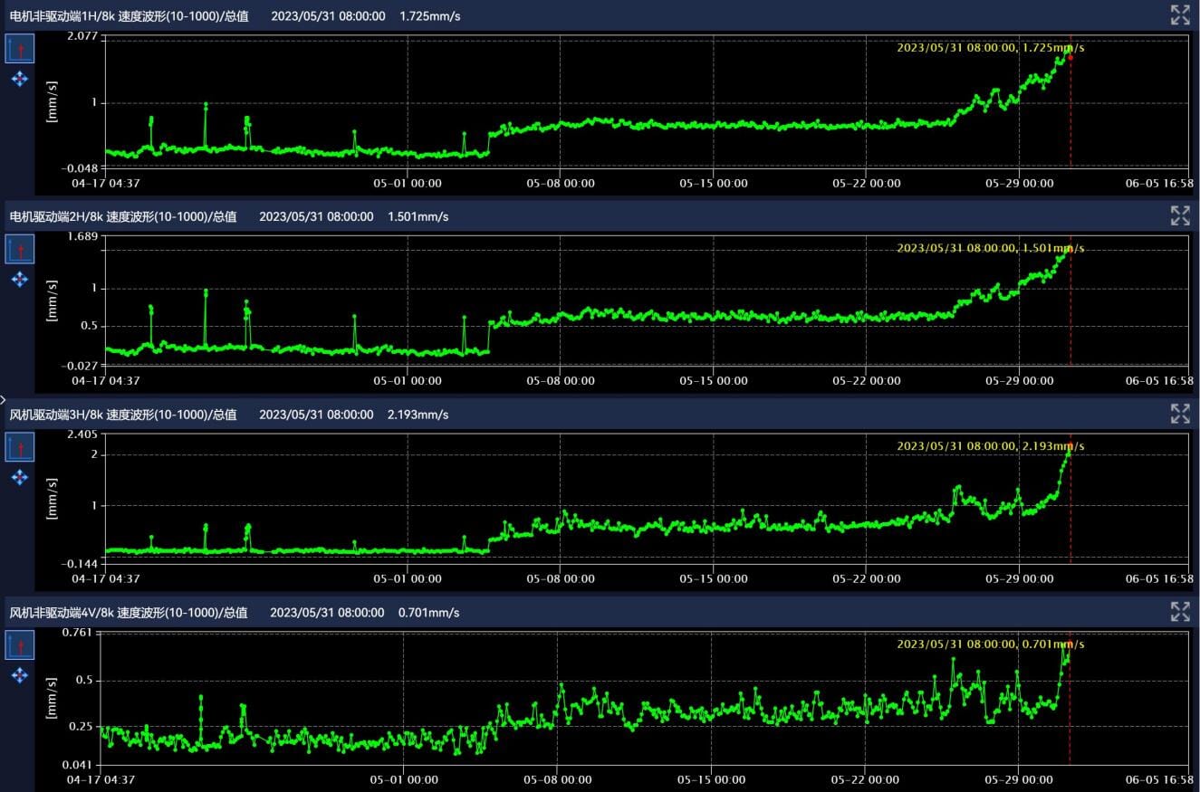
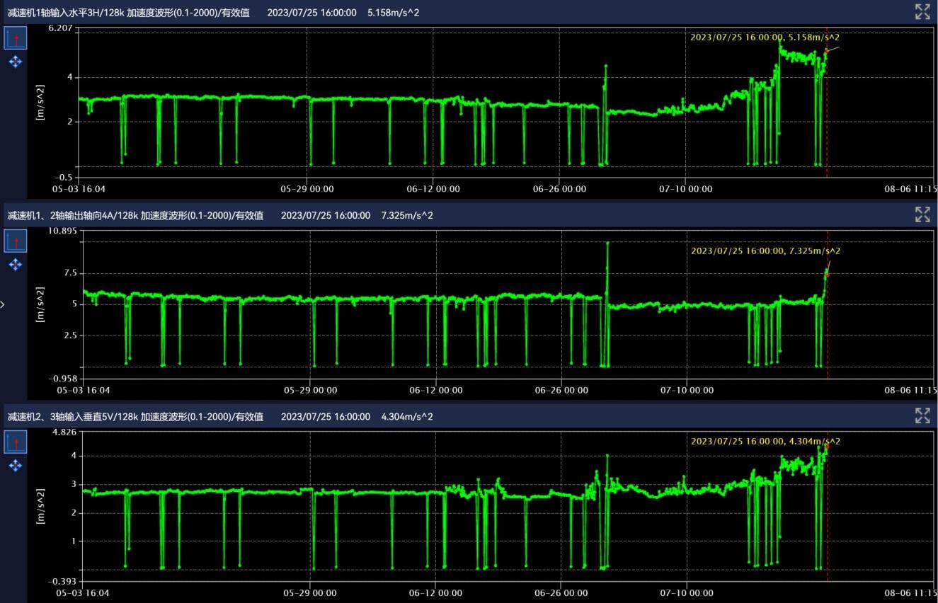
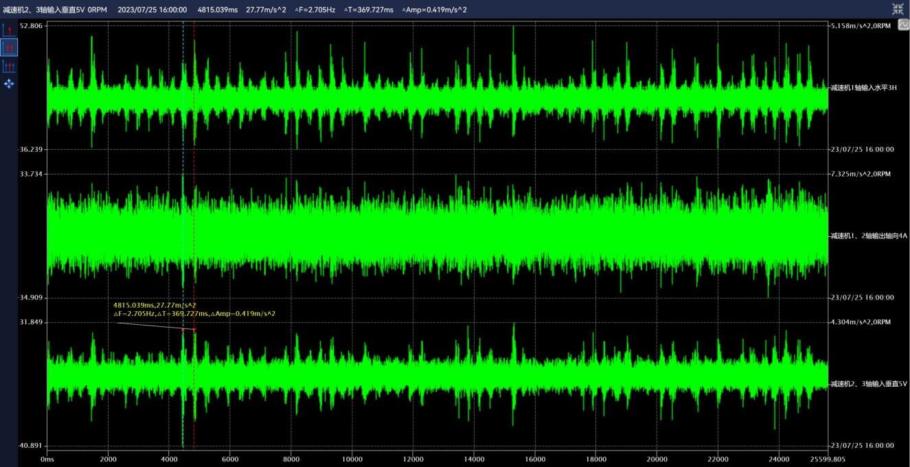
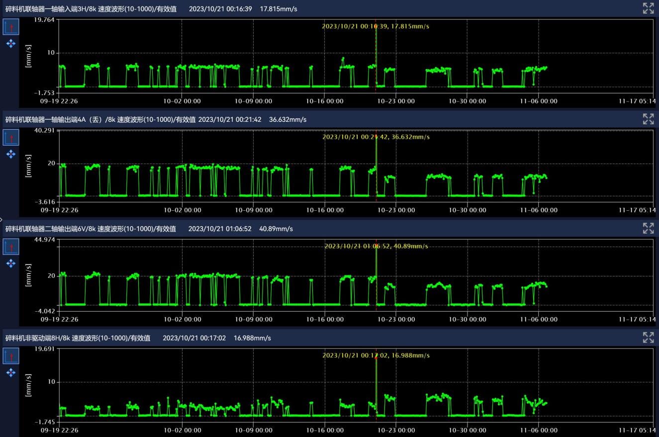
1. 300+ alarms and maintenance recommendations issued
2. Detected failures including:
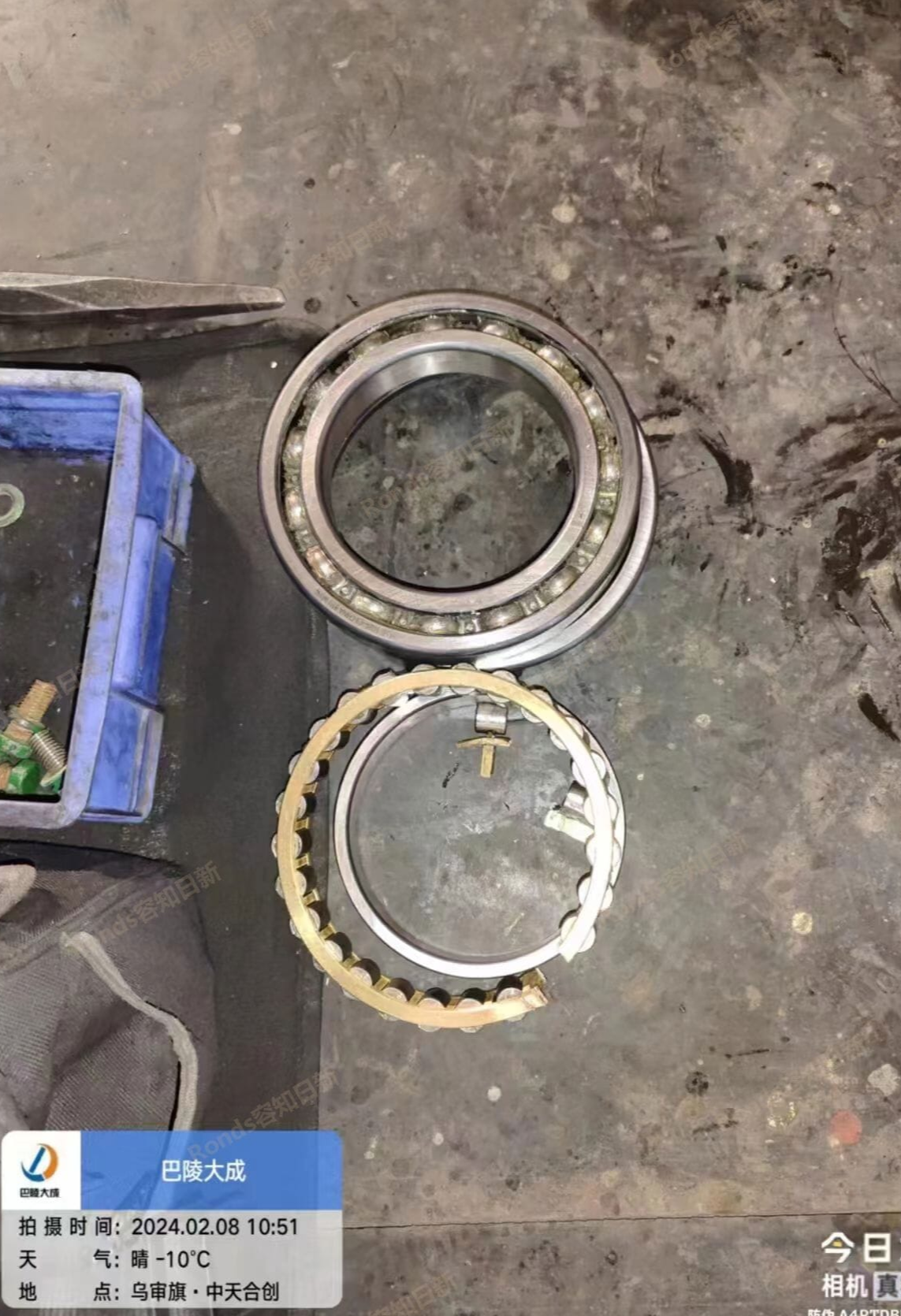
1) Bearing defects
2) Power frequency abnormalities
3) Component wear alerts
Data-Driven Maintenance Optimization:
1. Monthly equipment health reports for all assets
2. Proactive hazard notifications
3. Data-supported maintenance planning
Standardized & Lean Management:
1. Implemented condition-based maintenance
2. Improved spare parts utilization
3. Reduced maintenance complexity
4. Achieved:
1) fewer over-maintenance cases
2) reduction in maintenance backlog

Success Cases


-

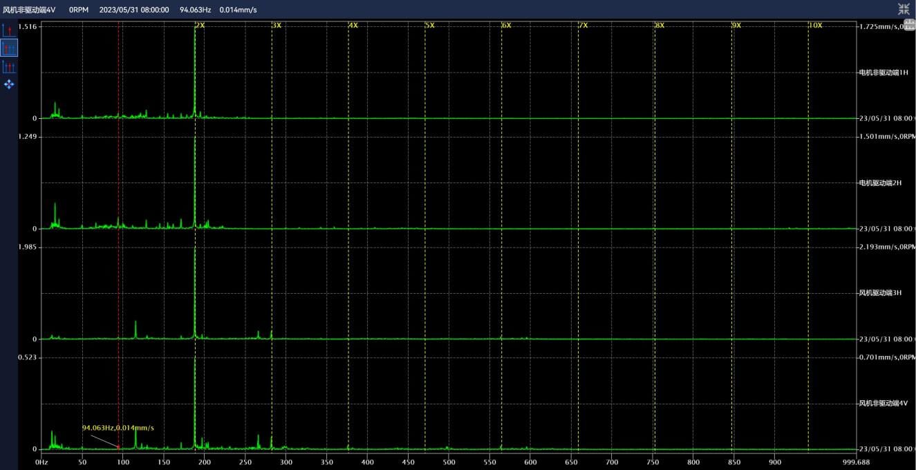
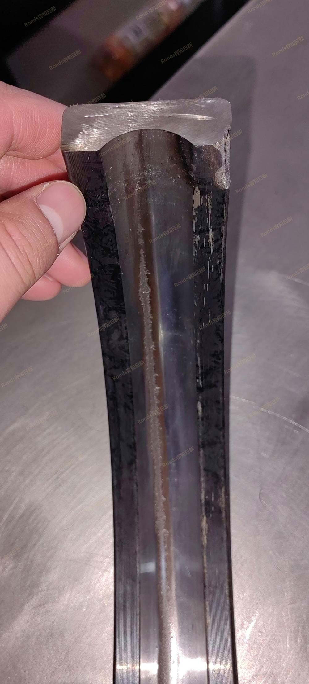
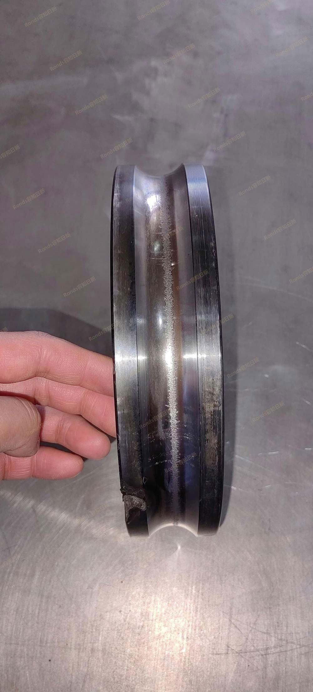
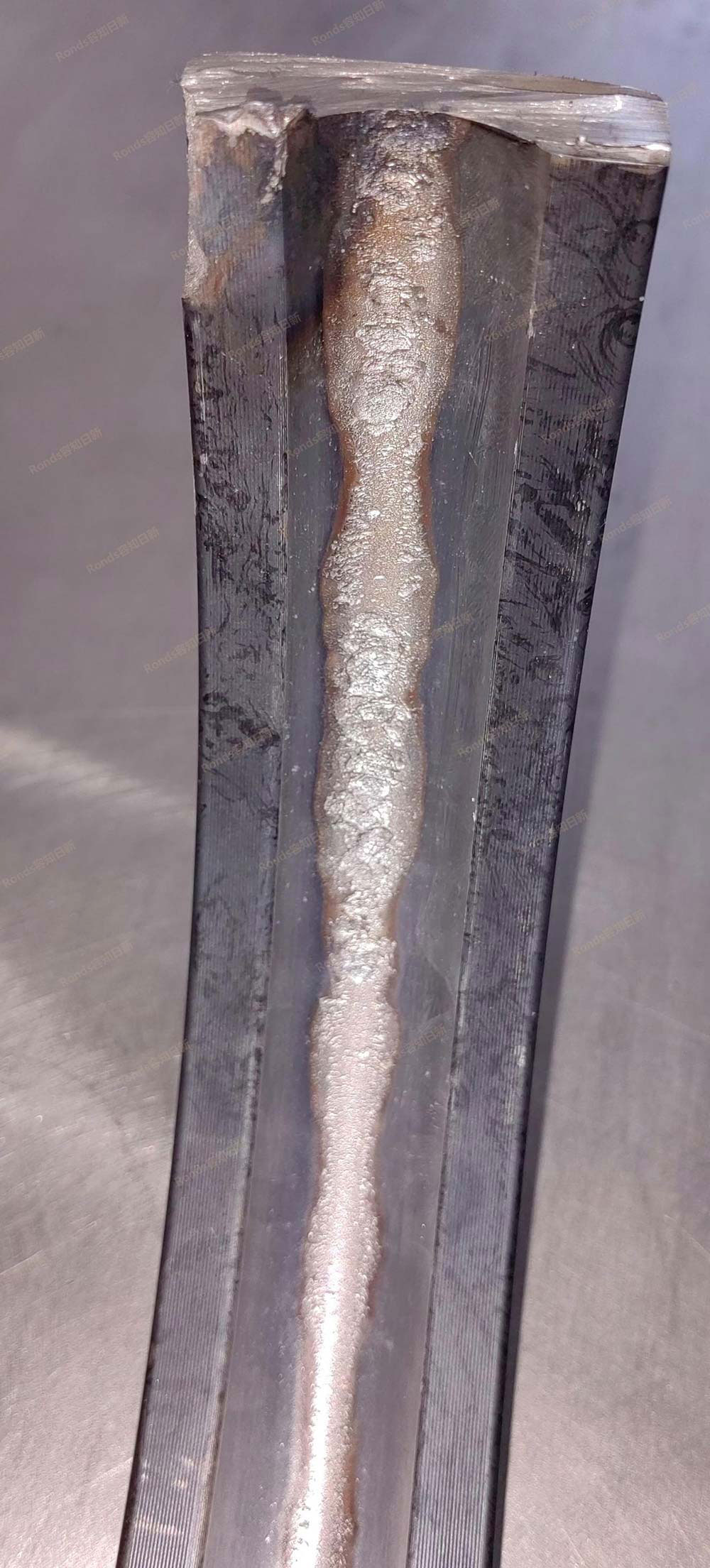
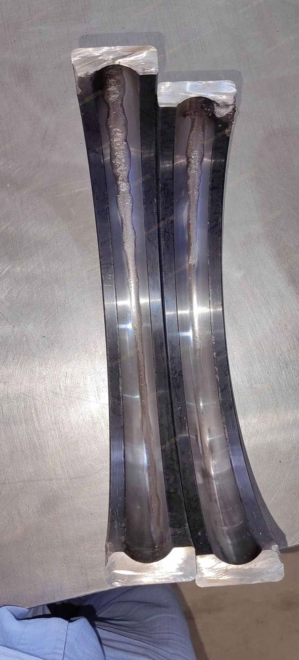
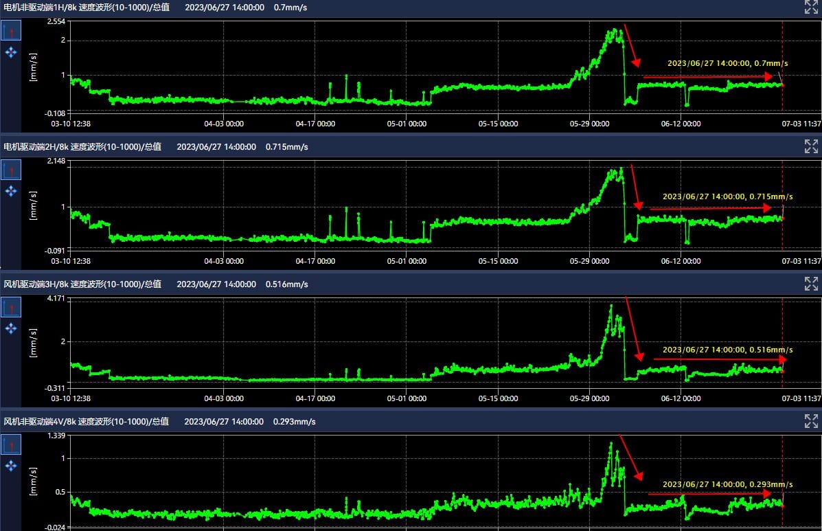
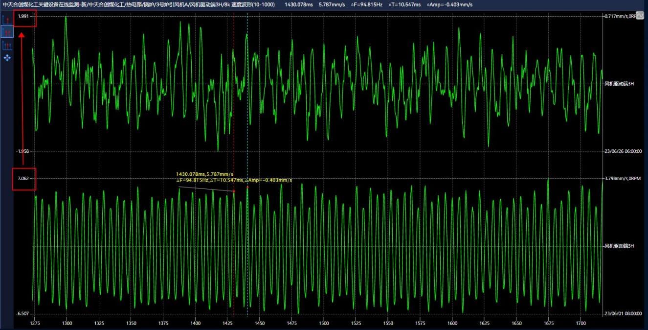
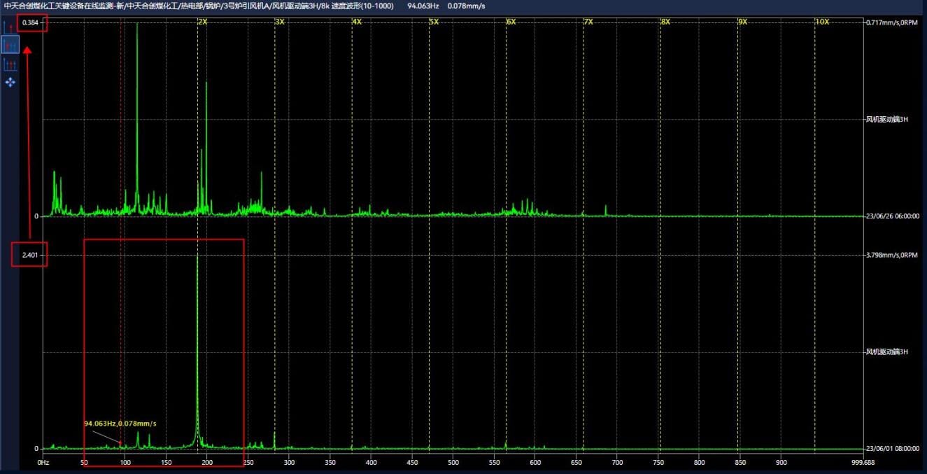
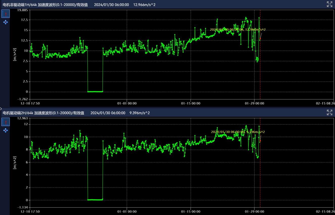
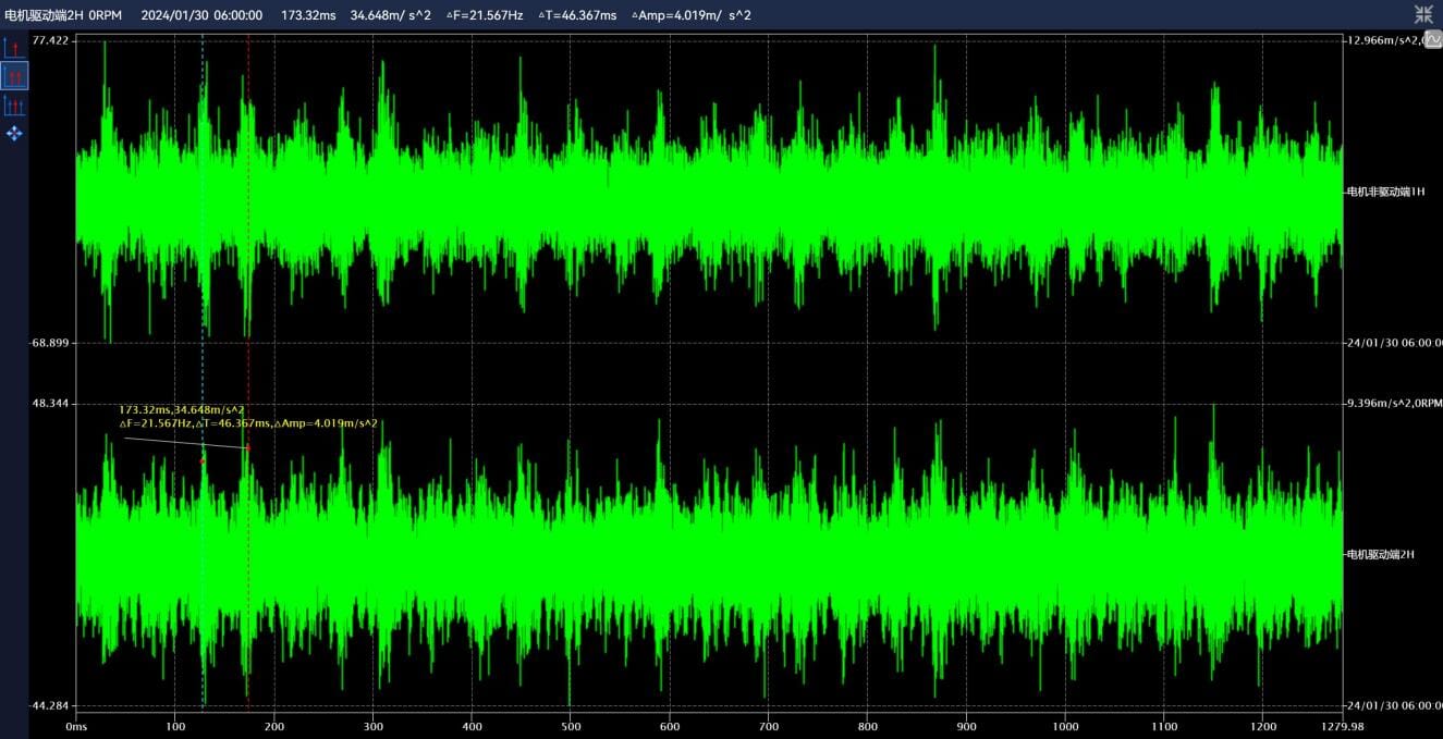
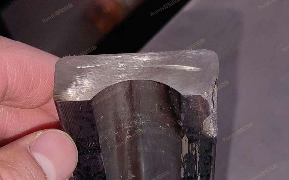 Zhongtian Hechuang Coal Chemical No. 3 furnace induced draft fan A

Learn More
-
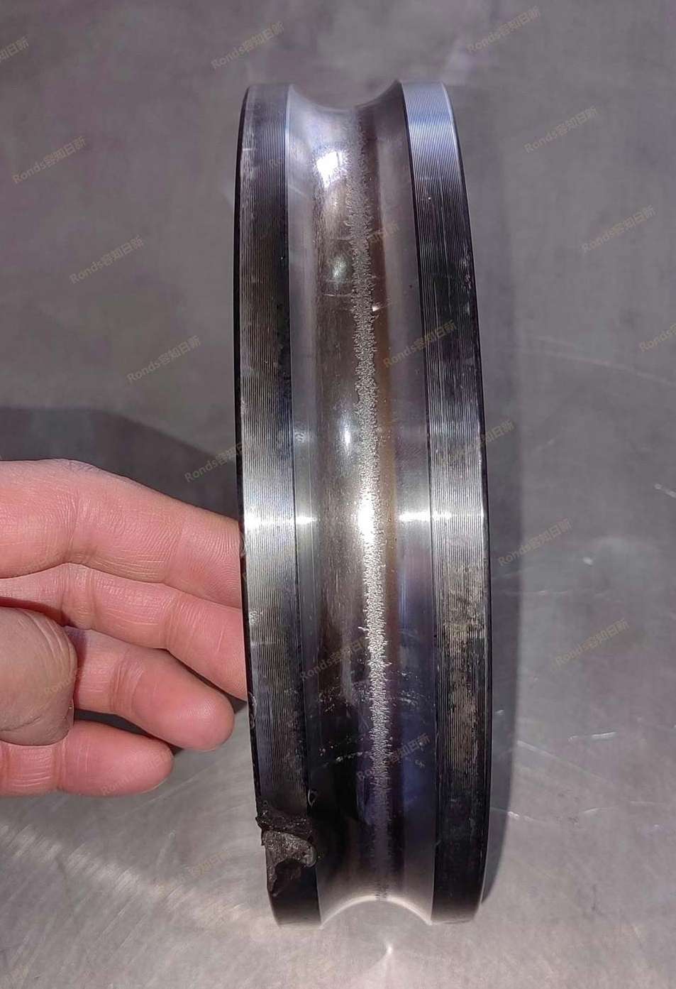
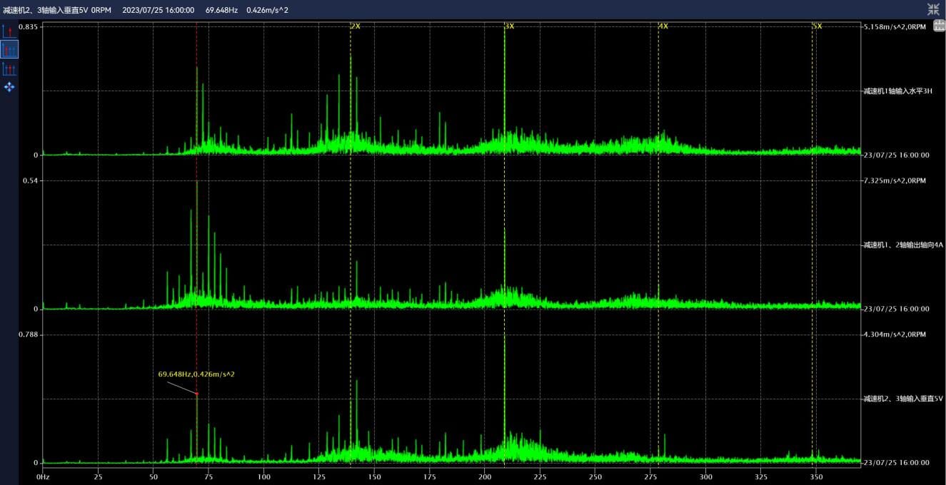
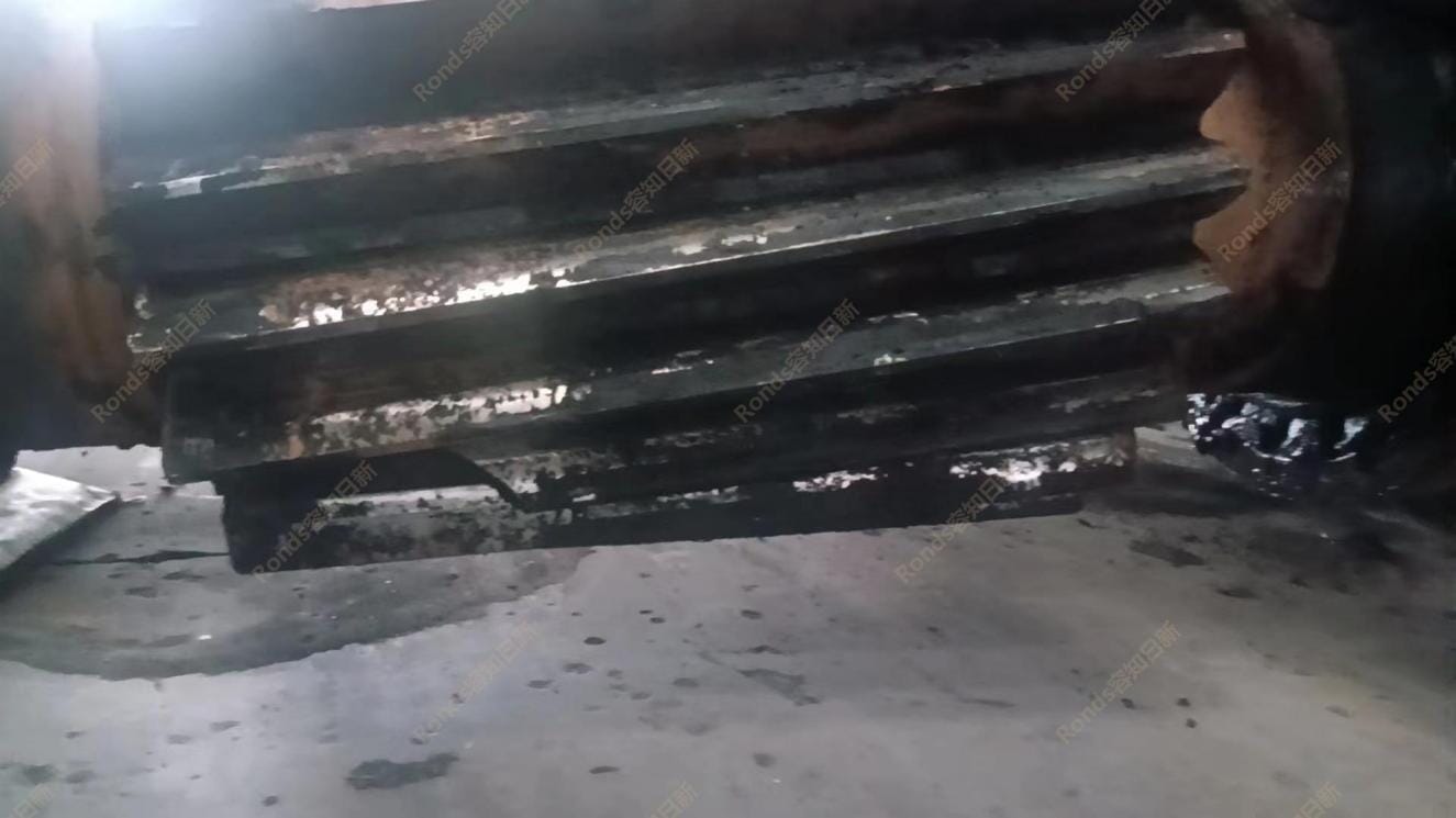
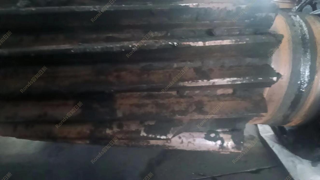
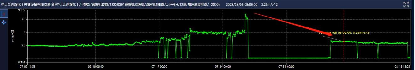
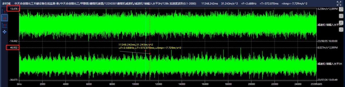
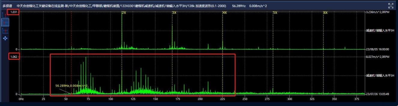
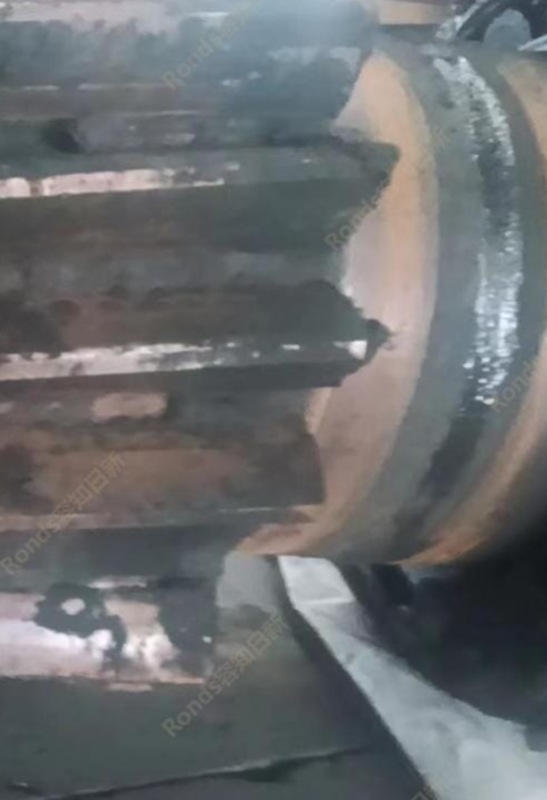
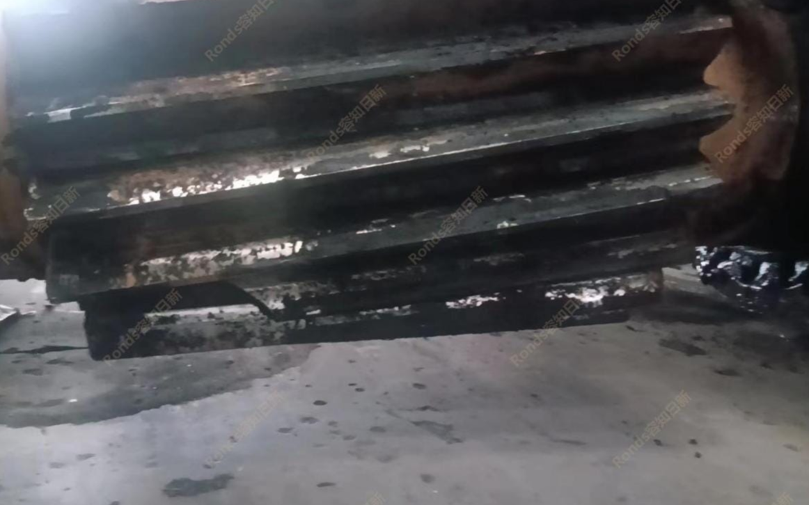 Zhongtian Hechuang Coal Chemical 122X0301 coal mill reducer
Learn More
-
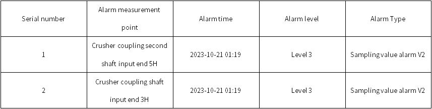
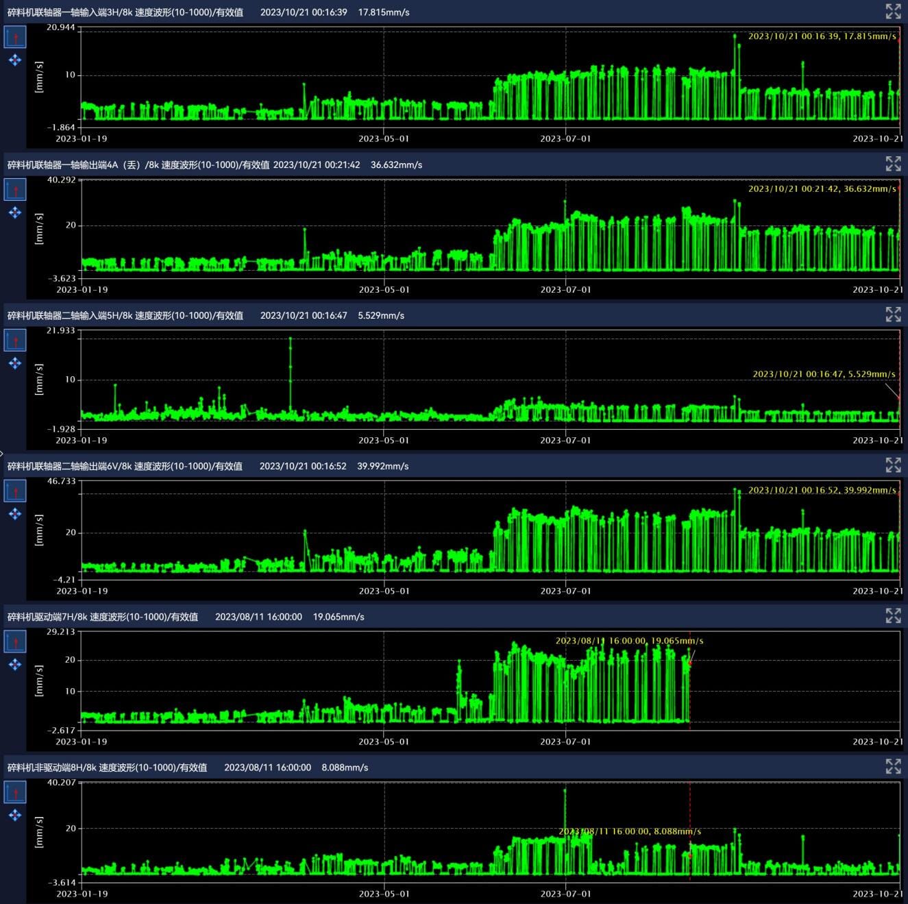
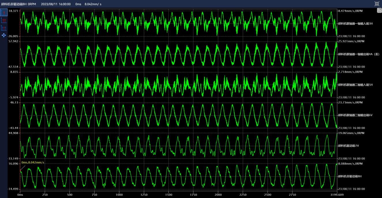
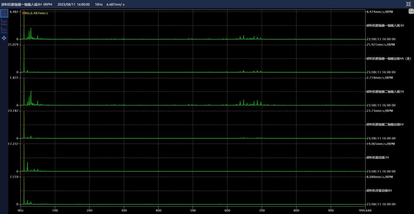
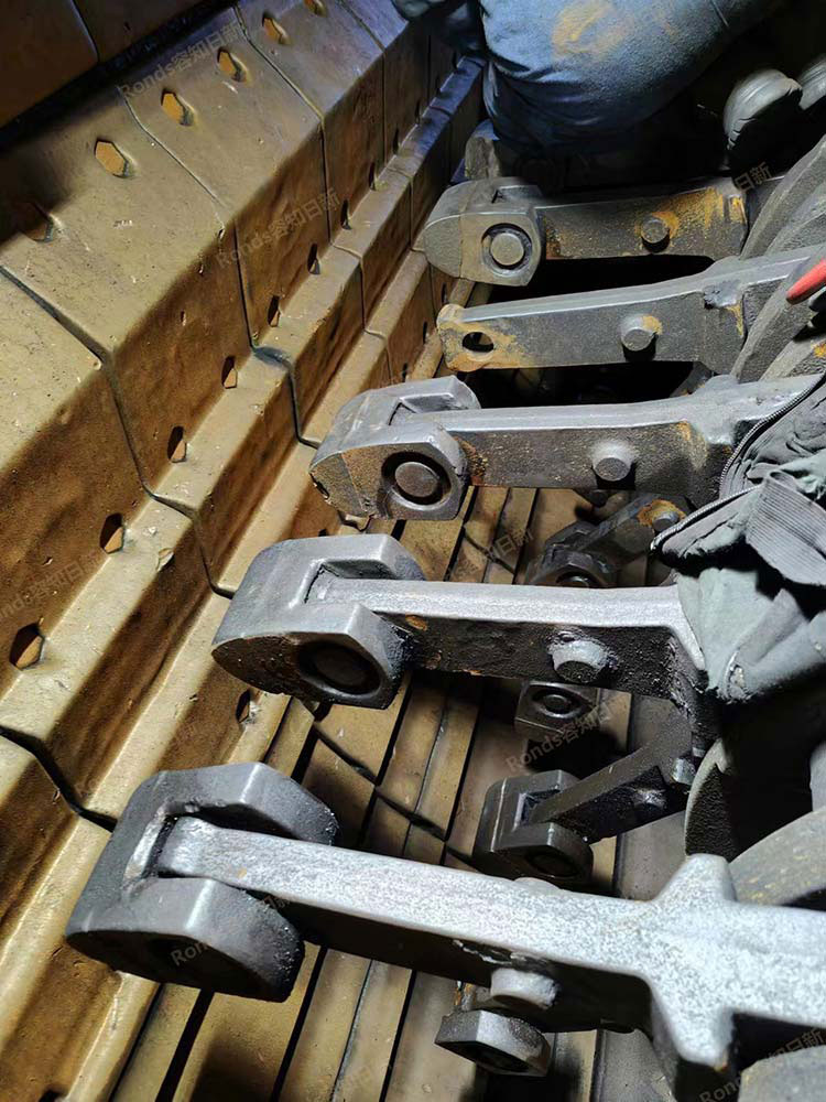
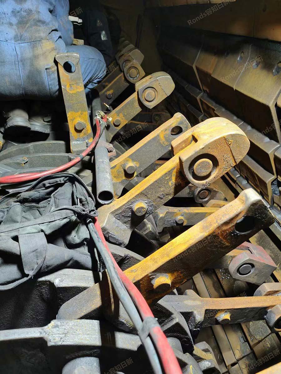
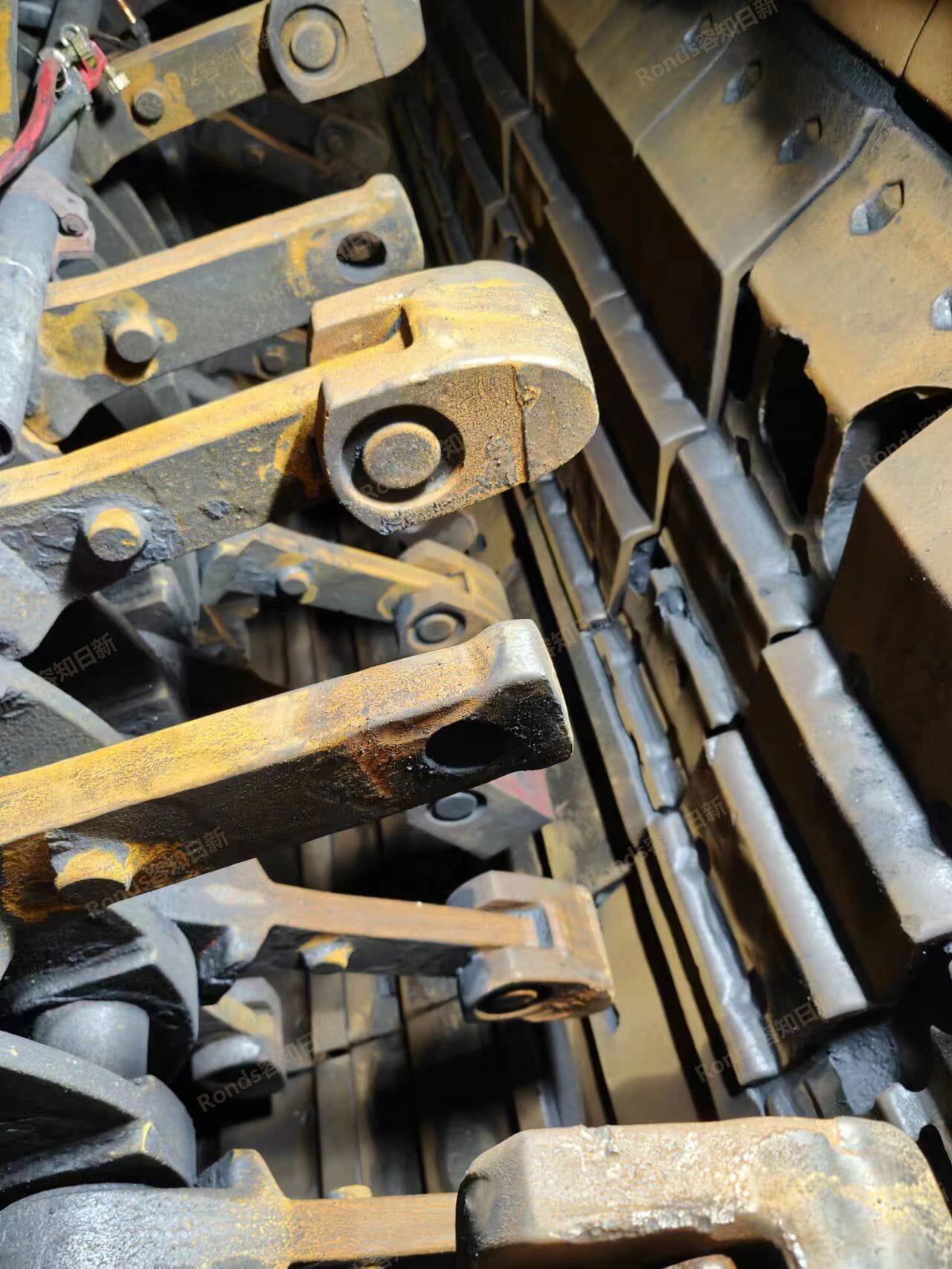
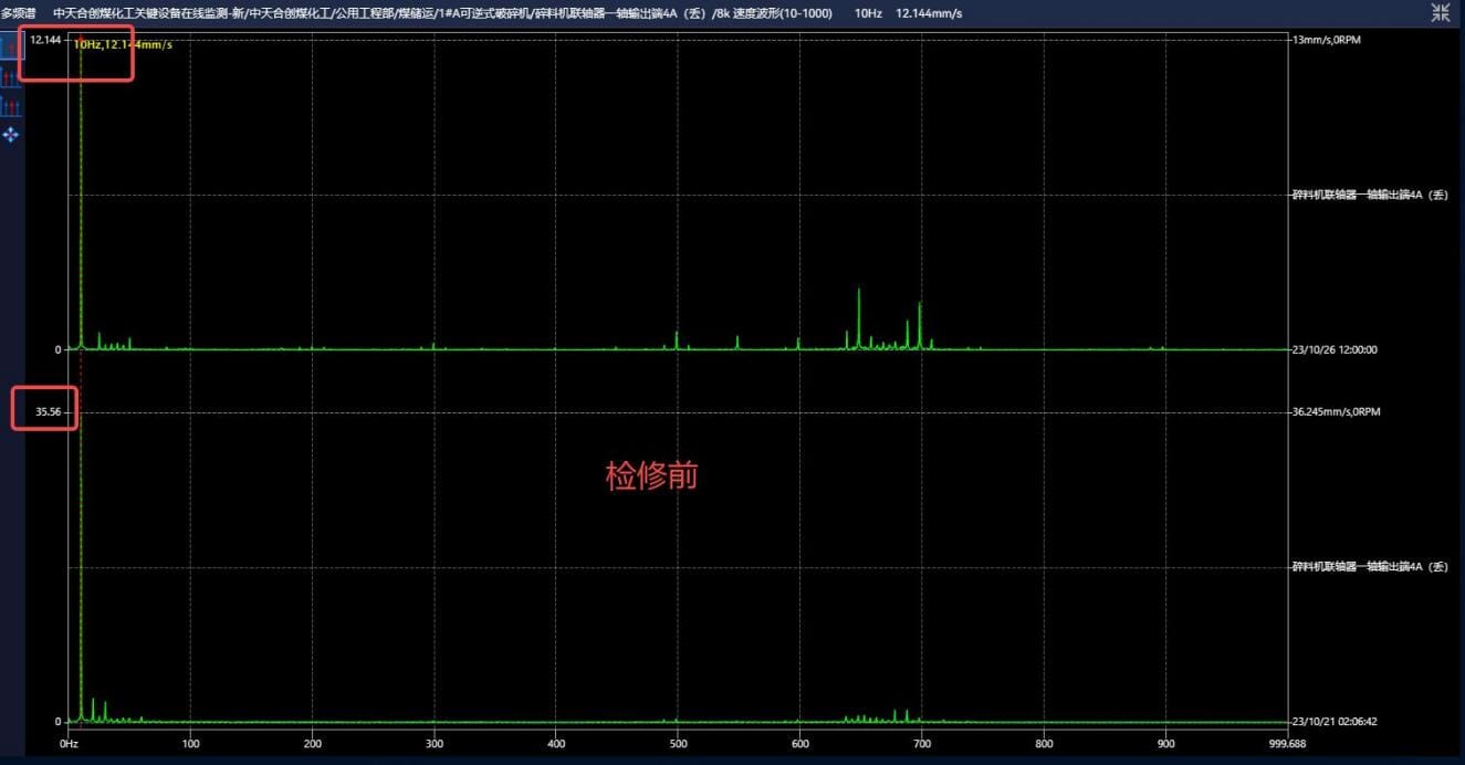
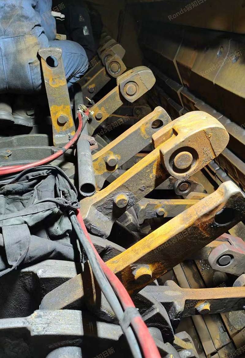
 Zhongtian Hechuang Coal Chemical 1#A reversible crusher
Learn More
-
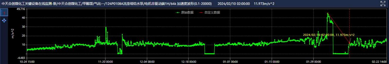
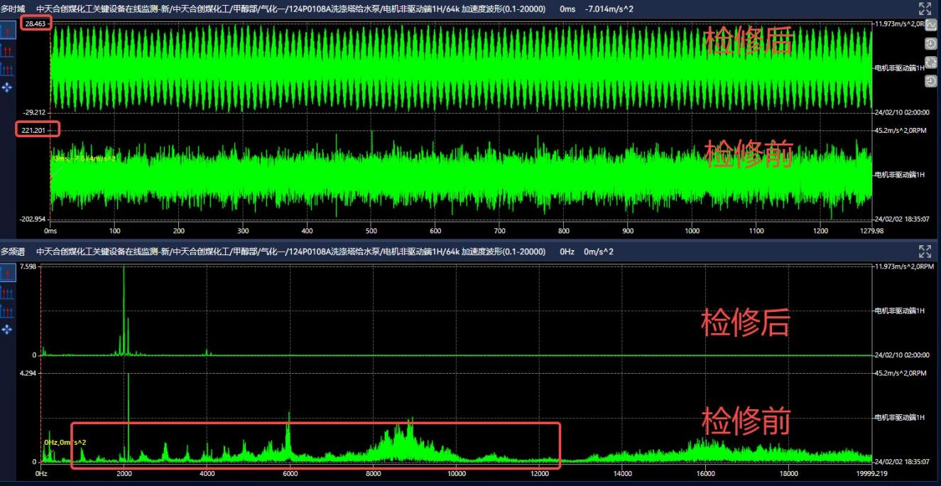
 Zhongtian Hechuang Coal Chemical 124P0108A Washing tower water pump
Learn More


Start Your Journey to Intelligent Industrial Equipment Maintenance

